4 To 16 Decoder Circuit Diagram
Decoder logic diagram and truth table Decoder in digital electronics Decoder outputs decoders construct active input enables
1 To 2 Decoder Circuit Diagram
Decoder logic Decoder 16 using circuit Digital logic
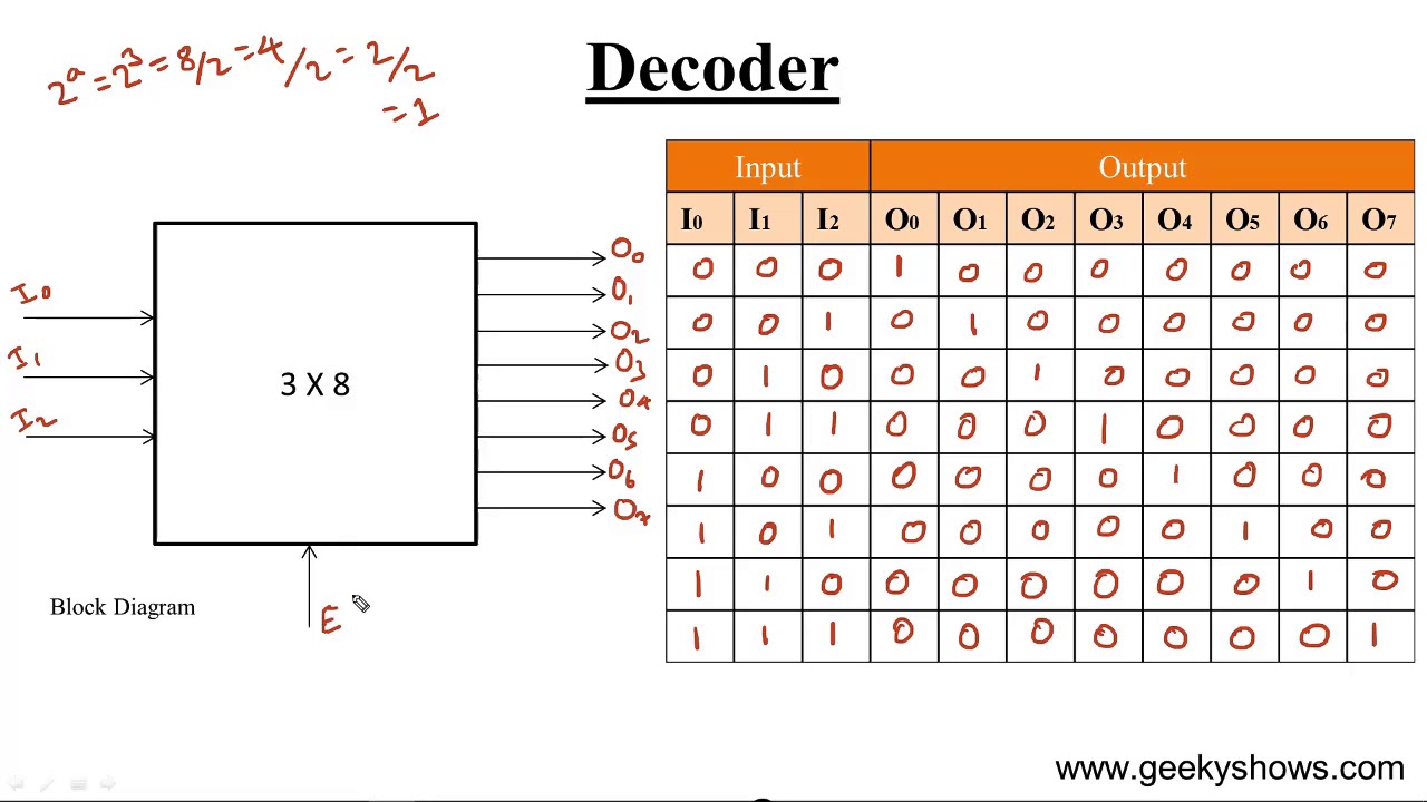
3 to 8 decoder circuit
Schematic diagram of the decoder_4_to_16 module.Decoder bcd decimal encoder 4 to 16 decoder circuit diagramDecoder decoders circuit priority logic encoders.
Decoder binary inputsHow to design a 4 to 16 decoder using 3 to 8 decoder Decoder logic1977 oldsmobile cutl wiring diagram.
4 16 decoder circuit diagram
Decoder diagram schematicDecoder decoders vhdl implement 2x4 4x16 verilog rtl solved 52e shown 4 to 16 decoder : example: 4-to-16 decoder using two 3-to-8 decodersImplement 4x16 decoder using 2x4 decoder [ easy way].
Decoder encoder ic circuit using circuits electrical projects line name operationDecoder decoders stack outputs 4 to 16 decoder circuit diagramDecoder, 3 to 8 decoder block diagram, truth table, and logic diagram.

Decoder logic diagram and truth table
1 to 2 decoder circuit diagramSchematic diagram of 4-to-16-line decoder with functional blocks Hybrid set-cmos based 2 to 4 decoder circuit in 22 nm technologyCircuit diagram of 4 bit decoder.
Decoder 4 bit to 16 lineBinary decoders: basics, working, truth tables & circuit diagrams Decoder circuit diagram and truth tableBinary decoders using logic gates.

3 to 8 decoder circuit diagram
Decoder input combinationalDecoder bcd voltmeter Block diagram of the 4 to 16 decoder.Using decoder 32 16 enable circuit schematic circuitlab created logic.
Solved design a 4-to-16 decoder using 2-to-4 decoders onlyEncoder and decoder 3 8 decoder circuit diagramDecoder digital electronics truth table javatpoint diagram.

Decoder logic diagram and truth table
Decoder logic block outputsEncoder and decoder circuits using ic 74148 & 74138 2 4 decoder circuit diagramWhat is a decoder? operation, types and applications.
4 to 16 decoder : example: 4-to-16 decoder using two 3-to-8 decodersGates decoder decoders Decoder cmosDecoder logic diagram and truth table.

Decoder circuit 16 binary decoders truth diagram applications block two
3 to 8 decoder circuitDecoder 16 two decoders circuit made properly working logic Decoder 2x4.
.


